Introduction: The Mathematics of Tension
Long span steel warehouse stability relies entirely on diagonal tension. Brace rods must fit perfectly. Cut them too short in the shop, the field crew cannot engage the threads. Cut them too long, the turnbuckle bottoms out before tension is achieved. A loose rod is dead weight. The b
uilding will rack in the wind. Steel structure rod bracing calculation requires absolute mathematical precision. No guessing.
1. Rod Segmentation Limits
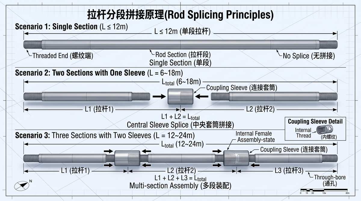
You cannot transport or install a 20-meter solid steel rod. It bends. It gets destroyed in shipping. We segment them.
-
Ø12 to Ø20mm: Single continuous rods are strictly capped at ≤ 12.0m.
-
Ø22 to Ø33mm: Heavy rods are strictly capped at ≤ 6.0m. For mega-spans, you mandate a 2-rod (up to 18m) or 3-rod (up to 24m) assembly. Connect them using turnbuckles.
2. Brace Rod Parts Specification Chart & Fabrication Length (L_fab)
Fabrication length (L_fab) is not the diagonal distance (L_diag). You must apply modification constants. Bevel washers add length because the rod passes through the web. Clevises and turnbuckles subtract length because the hardware occupies physical space in the diagonal path.
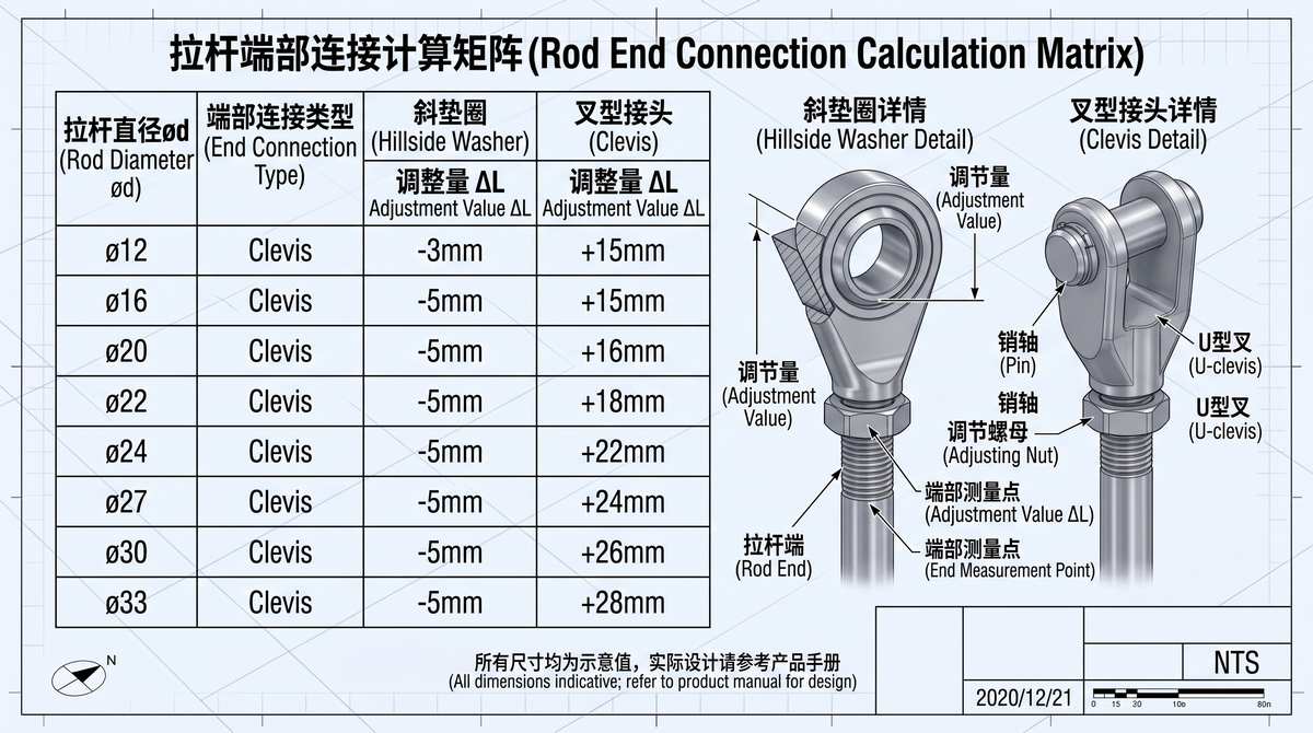
Follow this exact matrix.
| Rod Dia. (Ø) | End Connection A | Center Connection | End Connection B | Fabrication Length Formula (L_fab) |
| Ø12 / Ø16 | Bevel Washer (BW) | None | Bevel Washer (BW) | L_diag + 150 mm (+75mm per BW) |
| Ø12 / Ø16 | Bevel Washer (BW) | Turnbuckle | Bevel Washer (BW) | L_diag + 50 mm (+75×2 – 100) |
| Ø16 | Bevel Washer (BW) | Turnbuckle | Clevis Pin | L_diag – 125 mm (+75 – 100 – 100) |
| Ø16 | Clevis Pin | Turnbuckle | Clevis Pin | L_diag – 300 mm (-100×3) |
| Ø20 / Ø22 | Bevel Washer (BW) | None | Bevel Washer (BW) | L_diag + 200 mm (+100mm per BW) |
| Ø20 / Ø22 | Bevel Washer (BW) | Turnbuckle | Bevel Washer (BW) | L_diag + 100 mm (+100×2 – 100) |
| Ø20 / Ø22 | Bevel Washer (BW) | Turnbuckle | Clevis Pin | L_diag – 100 mm (+100 – 100 – 100) |
| Ø20 / Ø22 | Clevis Pin | Turnbuckle | Clevis Pin | L_diag – 300 mm (-100×3) |
| Ø24 ~ Ø33 | Clevis Pin | Turnbuckle | Clevis Pin | L_diag – 300 mm (-100×3) |
3. Wind Bracing Pretensioning Techniques
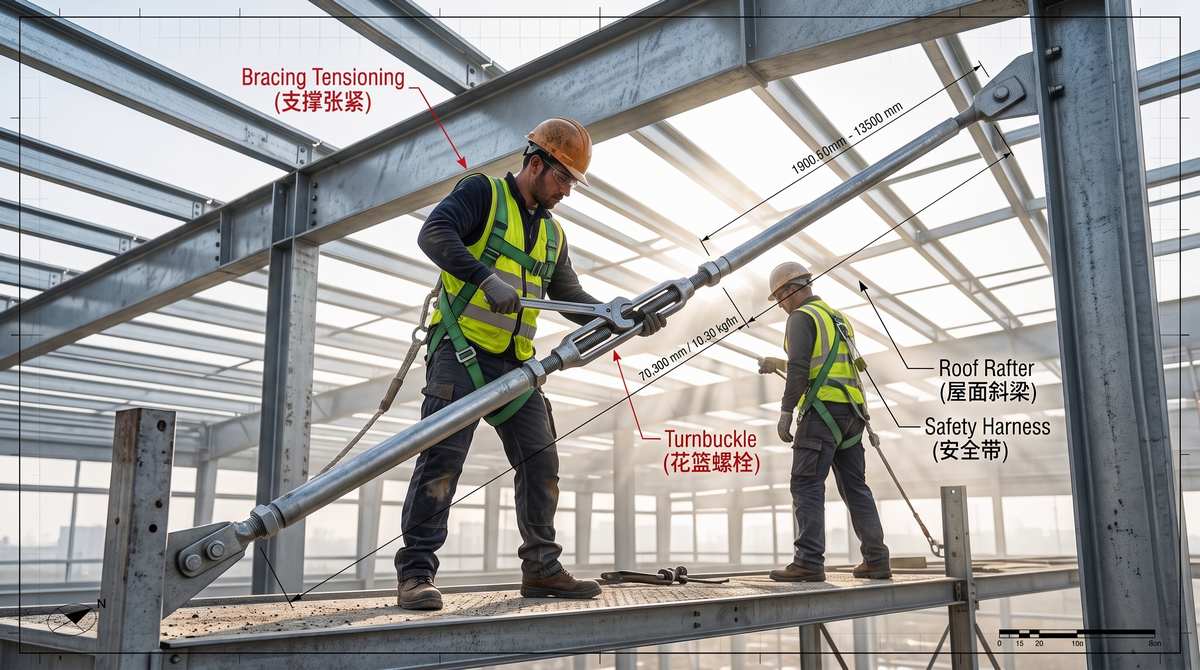
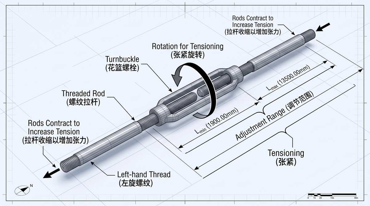
Installation dictates performance. Plumb the primary frames first. Never use brace rods to pull a building into plumb. Once the frame is square, spin the turnbuckle. Apply massive tension. Strike the rod with a steel hammer. It must ring sharply like a guitar string. A dull thud means it is loose. Tighten it again. Once tensioned, lock the jam nuts immediately to prevent vibration back-off.
4. The Web Stiffener Clash Rule
Detailers mess this up constantly. A diagonal brace hole lands exactly where a transverse web stiffener is located. The bevel washer hits the stiffener. It won’t sit flat. The connection is dead.
The Rule: Split the stiffener. Relocate it. Mandate a strict minimum clearance of 100 mm from the slotted hole center to the edge of any stiffener plate. Give the hardware room to breathe.