
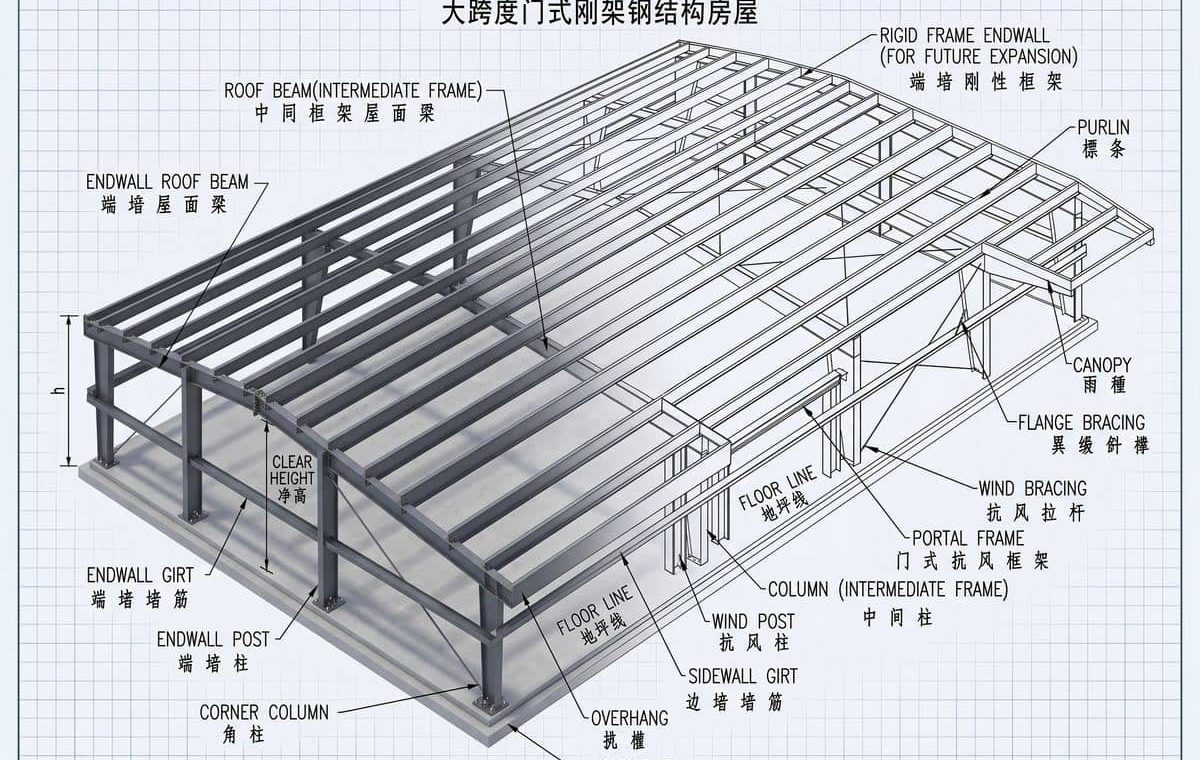
Introduction: The Backbone of Industrial Architecture
Primary rigid frames dictate the survival of a Pre-Engineered Building (PEB). Clear span. Eave height. Absolute load capacity. Get the frame typology wrong—Single-Span or Multi-Span—and your foundation costs explode. Steel tonnage spirals out of control. Interior facility space becomes entirely useless.
1. Understanding Portal Frame Classification
-
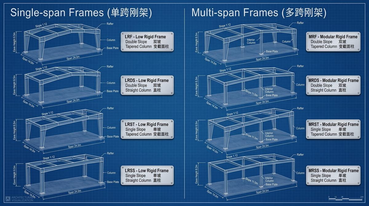
LRF (Low Rigid Frame / Tapered Columns): Variable-depth columns and rafters. The section depth hits maximum at the knee moment joint. Why? Bending stress peaks here. The profile tapers down toward the pinned column base and intermediate rafter splices. Optimal clear span: 15m to 36m (50ft to 120ft).
-
LRDS (Low Rigid Frame / Straight Columns): Uniform-depth vertical columns. Tapered roof rafters. Engineered specifically to maximize interior clearance for heavy pallet racking or machinery.
-
MRF (Modular Rigid Frame / Tapered Exterior): Introduces interior pipe or tube columns. Rafter spans shrink. Bending moments (M ∝ wL²) drop instantly. Frame weight drops. Mandatory for massive facilities spanning 30m to 120m+.
-
MRDS (Modular Rigid Frame / Straight Exterior): Straight sidewall columns combined with internal support pipe columns.
| Frame Type | Columns | Rafters | Best Application | Span Range |
| LRF | Tapered | Tapered | Standard industrial workshops, logistics warehouses. | 15m – 36m |
| LRDS | Straight | Tapered | Facilities requiring high-level racking/equipment against walls. | 12m – 30m |
| MRF | Tapered | Tapered | Mega sorting centers, multi-span manufacturing bases. | 30m – 120m+ |
| MRDS | Straight | Tapered | Multi-span facilities needing flat interior sidewalls. | 30m – 90m |
2. The Engineering Genius of Tapered Sections
Hot-rolled constant-depth beams waste steel. PEB frames leverage tapered (variable-depth) members. The web depth d(x) perfectly mirrors the bending moment envelope M(x).
The elastic section modulus Sx(x) is continuously tailored along the frame: Sx(x) = Ix(x) / y_max(x) ≈ [tw · d(x)²] / 6 + Af · d(x)
This structural logic locks the bending stress σ(x) = M(x)/Sx(x) directly at the allowable design limits (≤ 0.90 fy). Steel tonnage drops 15% to 25% against hot-rolled sections. Pure material efficiency.
3. Geometry Definition Parameters
| Parameter | Engineering Definition |
| Building Length (L) | Net distance between the outside structural lines of end walls. |
| Building Width (W) | Net distance between the outside structural lines of sidewalls. |
| Eave Height (Heave) | Vertical distance from finished floor level (±0.000) to top of eave purlin. |
| Clear Height (Hclear) | Vertical clearance from finished floor level (±0.000) to the lowest working point of the rafter bottom flange. |
| Roof Slope (θ) | Expressed as vertical rise over 12 horizontal units (e.g., 0.5:12 = 2.388°, 1.0:12 = 4.764°). |
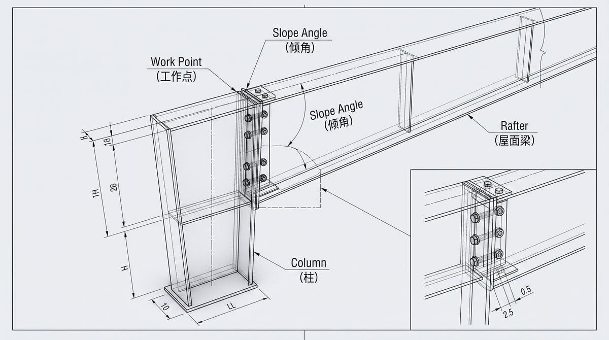
| Work Point (WP) | Theoretical intersection of component centerlines or axis lines. |
4. Material Specifications: Q345B Steel Engineering performance dictates material. Specs are absolute.
-
Yield Strength: ≥ 345 MPa (plates/tubes ≤ 16 mm).
-
Tensile Strength: 470 ~ 630 MPa. Elongation: ≥ 21%.
-
Carbon Equivalent (CEV): ≤ 0.40%. Critical for cold-climate weldability. Never ignore this.
-
Welding Standard: AWS D1.1 and GB 50205. 100% Ultrasonic Testing (UT) on full-penetration butt splices. Zero defect tolerance.
-
Surface Preparation: Centrifugal shot blasting to ISO 8501-1 Sa 2.5. 60~80 μm epoxy zinc-rich primer. Stop corrosion before assembly.
5. Column Length Calculation Formulas (SPL-1 Low Eave) Fabrication relies on exact trigonometric geometry.
-
θ = arctan(X / 12) -
C = Design Depth / cos(θ) -
D = B · tan(θ) -
E = C - D -
F = G - A / cos(θ) ≈ G - A -
Fabrication Column Length =
H_frame - (E + F) ± Base Recess Height